POUL LADEGAARD DESIGNED A WELL FUNCTIONING TANGENTIAL ARM MORE THAN 20 YEARS AGO. IN THE YEARS THAT HAVE PASSED, MANY EXPERIMENTS HAVE BEEN CARRIED OUT. THESE HAVE LED TO AN AIR ARM THAT CAN BE BUILT IN AN AFTERNOON.
Translated into English by Thomas Dunker
(pardon occasional clumsy language. I hope it's understandable. -Tom)
Partly we are seeing the end of a technology about to be outrun by a newer, perhaps more potent, yet also more alienating technology. Partly, the old analog technology now has reached its mature stage where it is more fun than ever before, where the experience gathered is the greatest and where everyone knows what it's all about.
Furthermore, building your own tone arm is still something most people can do and get away with decent, maybe even superb results if the necessary craftmanship is present along with good ideas. The emergence of air arms in the past few years has shown new possibilities and given a lot of inspiration. In this respect, this article will give some hints to a DIY arm that not only is extremely affordable, demands no special tools but also represents an almost perfect solution.
Solutions that combine simplicity and practical realization of 'ideal' demands don't come suddenly. They are results of many years of evolutionary development around my own designs combined with close encounters with the countless arms that have passed the critical inspection in the test lab.
A recapitulation of the most important experience and theoretical consider- ations made along the way may be useful.
All the others have probably 'made mistakes' somewhere or neglected an 'important' optimization. So the clue is to find a couple of points that seem to have been ignored and which can fuel the enthusiasm of the home designer.
I soon realized that the fundamental problem with a radial arm, namely the mistracking angle, was the root of all evil. First, it is minimized by giving the arm the familiar offset angle. Thereby, the skatingforce is not eliminated. Rather, it increases, but is usually made easier to correct. However, it never gets ideal. The skating force depends on the friction between the record groove and the stylus tip, and thereby also the cut of the stylus. It also depends on what is recorded on the record and whether or not wet playback is used...the quality of the vinyl...or other lubricants...
No! Optimizing error correction in the third/fourth level, that's not me.
A tangential arm became the only traversable road. Gone were all the afore- mentioned problems and one spinoff was apparent. The arm could be made shorter, lighter, and at the same time less resonant. This way experimentation with the matching of the effective mass to the high compliance of modern cartridges could be carried out quite freely. The arm resonance could, by an 'optimal compromise' be placed between 10 and 15 Hz. Hereby the sensitivity to the subsonic 'junk' on the record is reduced, and a fair reproduction of bass transients can still be had.
The result can be characterized as a geometrically optimized, light arm with a traditional cardanic suspension. But the mechanical problems associated with such a DIY design were substantial. Motor and gears for movement were not silent and naturally caused a stepwise movement of the arm. Countless experiments with gliding rails for the lateral bearing, contacts for starting and stopping the motor, lift design etc., was needed. Still, the operation was only for the expert and the numerous service interruptions were only accepted by the designe, who was put to the test. He knew how difficult they were to avoid. But times of musical enjoyment of the highest quality are remembered, often of several minutes' duration, and occasionally, an entire record side! And such moments are not easily forgotten by a do-it-yourselfer.
The basis was/is that there is only groove modulation in the horizontal plane at lower frequencies, below about 200 Hz, and that unwanted disturbance from warps on the record exist in the vertical plane. Due to the desire for the best possible transientresponse, the frequency response in the horizontal plane should be as smooth as possible, with a soft 6 dB/octave rolloff down towards 1-2 Hz, so that the only disturbance from eventual excentricity can be eliminated.
In the vertical plane the goal is to achieve the best possible rolloff of the warp frequency below 10 Hz. This means that the arm resonance should be between 12 and 16 Hz, and it can very well be undamped, so as to make the rolloff as steep as possible. In real life this means that the effective mass of the arm in the horizontal plane has to be 25-50 times greater than in the vertical plane, where in a light arm it's typically about 10 grams. The total effective mass of the moving system in the horizontal plane will then be in excess of 250 grams, and depending on its distribution, the total mass can get very high. One experiment was made.
The necessary inertia was achieved by using two large lead weights coupled to the vertical axis of a cardanic bearing, at a distance of about 5 cm at a right angle to the arm tube. The arm was now ready to be tested - at first as a radial arm. Listening tests as well as measurements confirmed the idea.
Now the challenge was to establish the tangential movement of the arm and arm base, now weighing more than 500 grams. It turned out to be a problem for the expert! Any sort of stepwise movement would instantaneously provoke any modest assymmetry in the arm and cause torque momentum, sending the diamond on an involuntary skating trip. Here, the idea of a new principle of movement had to be tried. The mass of a lead weight was to be transformed into the needed horizontal pull force using a pulley.
The problem now is to control the movement of the arm so as to ensure tangential tracking at all times. A heating wire slowly melting through stearin wax had the necessary properties and could by means of varying the electrical currrent be smoothly adjusted from a full stop to the necessary maximum speed. The wax was placed in a small tray in connection with the pulley wire. A wire in the wax along the edge of the tray was fastened to the arm base and thus it could steer/slow down the turning of the wax tray and thereby the movement of the arm.
The mistracking angle of the arm was measured with a photo cell, whose signal was converted into an evenly pulsating current in the heating wire.
It worked and yielded completely smooth and silent movement. But in order to get the whole thing working the heavy arm base had to be furnished with a great number of precision ball bearings as wheels and for steering.
Although it sonically fulfilled all expectations, it was to critical to use in practice. The very large inertia weights were very demanding to adjust to the required balance, and changing tracking force or replacing the cartridge would take hours. Furthermore, it turned out that the wax changed properties after having been melted through a few times, and had to be replaced. Dust deposits on the roller rail of the heavy arm caused unwanted friction and service interruptions.
Soon the arm was covered with dust altogether, and the 'spare' Moerch DP-6 took over the daily duty with ease of operation and reliability that contrasted 'the second arm'.
The wax control is theoretically ideal, it even works in reality, but requires a carefylly chosen type of wax in order to become reliable.
Increasing inertia in the horizontal plane with side weights fastened to the vertical bearing is too critical to adjust practically and is very sensitive to disturbance.
Separating the arm resonances in the horizontal and vertical planes and the corresponding optimalization however, is beyond any doubt desirable.
Maybe an air arm could be the right way? But, even though the first ones I encountered in measurements for test reports were fascinating, their design was certainly not suited for kitchen-table cheating. Also, a number of details seemed less than well considered. It had to be possible to do it in a simpler way and to do it 'right'.
Independent of the design it is a welcome property of air bearing arms that they almost automatically have the desirable big difference in vertical and horizontal inertia. The whole mass of the arm contributes to horizontal inertia due to the translatory movement. It should be possible to use this in developing a good solution.
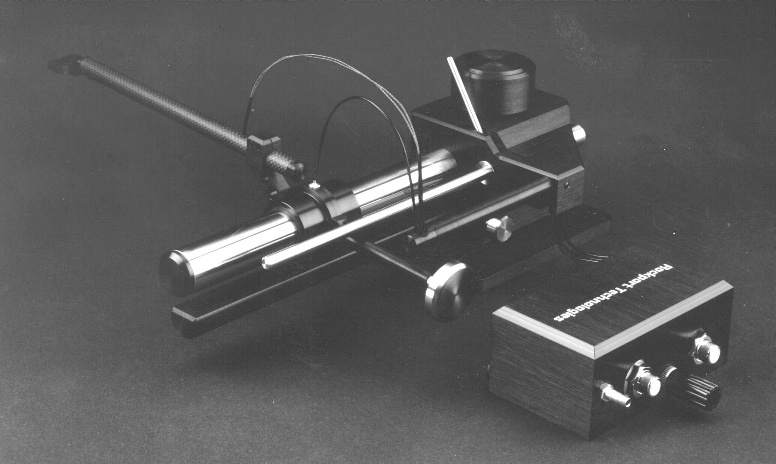
Johnny Soerensen's description of his 'Kolibri' arm in 'high fidelity' nr. 7/8 and 9 1990 was sufficient provokement. And if it hadn't been for the expensive 'laser hole' tube there would probably already be a copy on which to base new experiments.
One single idea, however, set of a minor avalanche and (almost) all the pieces of the puzzle fell together:
"An air arm based on angle profiles, where only the bearing for horizontal movement is air bearing, where the vertical movement is controlled with a traditional bearing based on balls, pins or knives."
This immediately gives the following advantages:
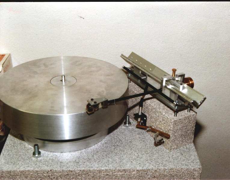
THE FIRST PROTOTYPE is based on a piece of standard 3x20x20 mm angle aluminum that was cut into a length of 30 cm for the arm base and 18 cm for the carriage. This gives the arm a net travel of 12 cm. This is sufficient to cover the engraved part of the record of about 10 cm and allows room for 'parking'.
After grating off corners and edges, the profiles were lightly honed together with a piece of fine sandpaper, coarseness 240 or finer (grade figures for sandpaper may vary from metric to imperial. Use your heads! -Tom) Coarser paper is not recommended. Loose grains may settle in the soft metal, causing disasterous consequences later. There is very little room when the thickness of the air film is less than 50 microns! There shouldn't be too great a need for polishing unless the profiles are very rough. Fine steel wool is recommended for finishing, and in many cases it will handle the whole job.
A helpful tool consisting of two strips of wood, for example 22x22 mm fastened to a wooden board so that the distance corresponds with the thickness of the profiles is almost indispensible. Partly, it protects the kitchen table, and partly it makes it a breeze to measure and drill the air holes from the outside of the profiles. Good results have been achieved when the holes are drilled along the middle axis of the profile (on the outside) and with a diameter of 2.5 mm, the holes placed 2 cm apart. Hereafter the holes should be grated off around the edges and you can polish again if necessary - or wait with the polishing until all the holes have been drilled. (RECOMMENDED!!!!!! -Tom) The holes can now be covered with tape, such as 3M Scotch or similar with long term durable adhesive. The final holes can now be made with a 0.3 mm wire or syringe. (I found that normal Scotch tape was a little bit brittle and the holes wouldn't get perfectly circular. I wound up using two layers of paper masking tape cut narrow and lined these with PVC insulating tape to ensure airtightness. -Tom)
All you need to do now is to close the angle profile at the back and to fit an inlet for the air hose. The easiest way to close it is to use another piece of aluminum, fastened with a strip of double sided tape. See sketches.
THE SECOND PROTOTYPE is built with anodized profiles measuring 2x20x20 mm. Here, no polishing is possible, so the surfaces had to be smooth from the beginning.
If the profiles have slightly different inner and outer angles, they can be made equal. Cover the long piece on the inside with aluminum foil and cover it with a thin layer of epoxy glue. Now the carriage piece can be pushed into the cement. After the cement has hardened, the carriage will fit perfectly with the bottom piece.
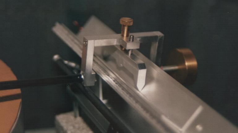
As a horizontal bearing, one with 3 mm ball bearings as well as one with 'hobby knife' blades have been tried. Details can be seen on photos and sketches. Both gave outstanding results.
The arm tube is a carbon fiber tube from a discarded Badminton racket with a lead block as counterweight. The arm is fastened to the bearing and cartridge with small clamps.
There is nothing particularly critical or expensive to anything in this design. Try first with the most easily available materials and methods.
Now one might fear that poorly centered records would provoke the stylus too much when it has to move so much 'baggage'. In the old days - in the age of radial arms - there was somethign called a 'skateometer'. It came from Dual and could be fitted instead of the cartridge so that one could see if it had been properly adjusted. With this fitted on a tangential arm, the effect of excentric records could be evaluated. On the arms desribed here, the load was typically around +/- 50 milligrams. This is insignificant compared to a normal tracking force of 1.8 grams. More critical is the adjustment of the arm base to perfect level. But here is yet another advantage of this design. Simply lift the arm tube off the carriage and see if the carriage remains still.
The optimal thickness of the air film can give rise to many considerations. Immediately one would assume that it should be as thin as possible. Thereby you get the leas vibration and a thinner film might give a desired damping in the horizontal plane. It's easy to experiment by varying the air supply. Based on preliminary results, an air film with a thickness of 50 microns will be sufficient. This can be achieved in practice and can be controlled with known strips of paper or foil by slipping them into the air gap. Normal 80 gram copier paper is about 80-90 microns thick. If that can pass, there is too much air. Normal LP audio tape is about 35 microns and standard cassette tape is down around 23 microns. As shown in one of the measurement graphs, a damping effect is noticed as the air film is reduced. But here it is possible that beginning friction begins to affect the response. The temporary conclusion is that it's a bad idea to base damping on the air bearing.
In order to get a precise picture of the performance of the arm down at a couple of Hz, we have developed a little vibrator to use in addition to test record measurements. It's a modified midrange speaker that can simulate a test record from 1-50 Hz. The results of measurements using this device completely confirm the test record measurements.
Of problems still awaiting solution is to establish some sort of damping of the resonant peak at 2.5 Hz. If this can be done, the arm will be more immune against external 'shaking'.
When a couple of ideas for solutions have been tried out they will be presented in this magazine and will be easily added to the existing arm. (No such improvements have surfaced yet. -Tom) But, under any circumstance it's almost a requirement for good results that it be mounted on a stable wall to remain in level. Thus, problems with picked up shaking will also be reduced.
Jeremy Epstein's Ladegaard arm FAQ
![]()